| Python Exemplary |
SERIAL PORT, GPS
![]()
The source code of all examples can be downloaded from here.
What is the RS-232C protocol? |
|
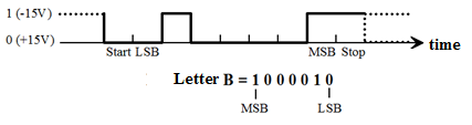
Although Bluetooth, Ethernet, or USB interfaces are commonly used for communication between a computer and peripherals (and I2C, SPI and 1-Wire for microcontroller systems), the communication over the serial interface (RS-232C) is still widespread. Traditionally the serial interface is still used to connect measurement devices (voltmeters, oscilloscopes, etc.) and to communicate with roboters, modems and microprocessor systems (e.g. downloading programs to the Arduino). Modern computers no longer have serial ports, however this problem can be easily solved with low cost USB-to-serial adapters. The format of the transmitted data is simple. It consists of chronologically transmitted data bytes. The transfer begins with a start bit, where the receiver calls attention to the pending data transfer. Then the data itself follows, including 5, 6, 7 or (usually) 8 bits. In order to facilitate an error correction, a parity bit may be sent which indicates whether an odd or an even number of bits were set, but the parity bit may also be omitted. The transfer is completed with one or two stop bits. In the idle state the sending and receiving devices are not synchronized with each other, i.e. the data transfer can begin at any time (asynchronous protocol). However, it is necessary that both devices agree upon the same time duration of a single bit. This is specified by the baud rate (in baud, bits/s) and can usually only be any of the standardized values 300, 600, 1200, 2400, 4800, 9600, 19200, 38400, 57600, 115200 baud. In addition, both devices can agree on a handshake (flow control), with which they inform each other whether they are ready for the data transfer. You can distinguish between a hardware and a software handshake depending on whether the handshake uses specific handshake pathways or whether it occurs using special ASCII characters (XON/XOFF) embedded in the data stream. A typical RS232 port configuration therefore comprises: Baud rate, the number of data bits (5, 6, 7, 8), the number of stop bits (1 or 2) , parity (none, odd, or even), handshake (none, hardware or software). Example: The flow of voltage during the transmission of the letter 'B', with the configuration 7 databit/no parity/1 stopbit looks as follows.
|
|
|
Serial ports on the Raspberry Pi |
|
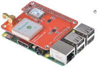
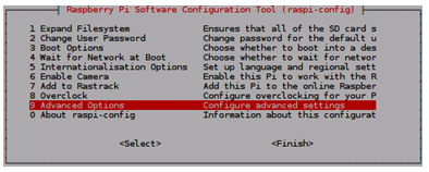
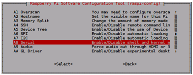
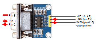
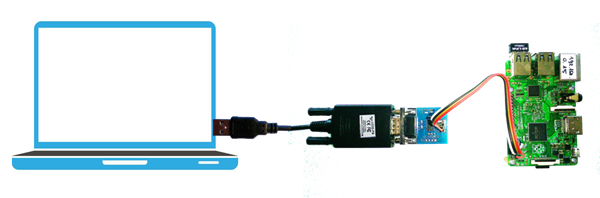
You have two choices to add a serial port to the Raspberry Pi, either over the GPIO connector or using an external USB-Serial converter. Since the Raspbian operation system supports the most common USB-Serial converters like the U232-P9 that you find on eBay and computer shops, it is recommended to connect external RS232-devices via USB. But sometimes you have breakout-modules with a serial interface that are directly connected to the GPIO header such as most GPS modules specially designed for the Raspberry Pi. In this case GPIO pins #8 and #10 are used as UART-TXD0 and UART-RXD0 data transfer ports. By default, the Raspberry Pi uses the GPIO serial ports to connect an external RS232 terminal as an alternative Linux shell. In early days of the Raspberry Pi this was a interesting alternative that remembers the good old days when terminals (and teleprinter) where the standard input-output devices for minicomputers and mainframes. Today, there are no more specially terminal monitors, but still virtual terminals (terminal emulators) for all common platforms. One of the most popular is PuTTY that can be easily installed even on the Raspberry Pi. If you want to use the GPIO port for serial communication other than a console, you must disable the console by the Raspi configuration dialog as follows: Use a attached keyboard/screen or a VNC connection and type in a console:
Serial:
and say No for a login shell:
|

|
|
GPIO serial communication with the Raspberry Pi 3 |
|
Unfortunately things changed a bit with the current version of the Jessie operating system for the Raspberry Pi 3. First the serial port name ttyAMA0 reserved until now for the GPIO serial communication was stolen by the Bluetooth driver. The GPIO serial port name is ttyS0 now. Second and more annoying is the fact that the serial port is not functioning because of the higher CPU core clock frequency. Proceed as follows if the GPIO serial port is used: In a console, open the file /boot/config.txt as sudo in the nano editor sudo nano /boot/config.txt and add the line core_freq=250 Then reboot: sudo reboot To access the serial port in your programs, you must use the port name ttyS0 instead of ttyAMA0 and everything should work as with the older Raspberry Pi models. It is not well documented whether the decreased core frequency influences the general behavior of the system. You can get information about the names of all serial ports with the command dmesg | grep tty If you find the text: console [ttyS0] enabled console [ttyAMA0] enabled the console is not disabled (see above how to disable it). |
|
|
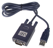
Serial communication using a Serial-USB converter |
|
|
|
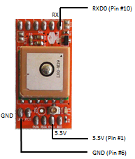
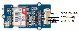
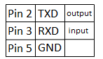
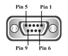
RS232 level converter for the serial GPIO port |
|
||||||
|
|
Experiment 1: Simulating a device connected via RS232 |
|
Sometimes you want to use the Raspberry Pi as controller or interface to a measurement device or a sensor that communicates via a serial connection. Aim:
Program:[►] # Serial1.py import serial import time port = "/dev/ttyAMA0" # Raspberry Pi 2 #port = "/dev/ttyS0" # Raspberry Pi 3 def readLine(port): s = "" while True: ch = port.read() s += ch if ch == '\r': return s ser = serial.Serial(port, baudrate = 1200) print "starting" while True: time.sleep(1) print "sending synch" ser.write("A") rcv = readLine(ser) print "received:", rcv Remarks: To avoid blocking the main loop may request data every second and accumulate any number of received characters by checking the number of characters nbChars in the input buffer and use read(nbChars) to get them altogether. Program:[►] # Serial2.py import serial import time port = "/dev/ttyAMA0" # Raspberry Pi 2 #port = "/dev/ttyS0" # Raspberry Pi 3 ser = serial.Serial(port, baudrate = 1200) print "starting" while True: time.sleep(1) ser.write("A") nbChars = ser.inWaiting() if nbChars > 0: data = ser.read(nbChars) print data Highlight program code
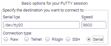
Remarks: sudo apt-get install putty and open PuTTY in an VNC session by clicking the icon in Menu | Internet. In the Basic options dialog check the button Serial and select /dev/ttyS0 for the Raspberry Pi 3 or /dev/ttyAMA0 for older versions.
|
|
|
Experiment 2: Use a GPS module and show current GPS information |
|
Commercial GPS modules are typical devices that use the serial protocol to transmit data to an external device. Most of them do not require any special setup nor commands to function. When powered up, they send lines of ASCII text in a special format, called NMEA messages, that can be received as string with with a simple readline() call. Normally the baud rate is 9600 baud by default, but you should consult the data sheet to check this. Aim: Attach a GPS module to the Raspberry Pi and capture data lines in the console.
Program:[►] # Serial3.py import serial port = "/dev/ttyAMA0" # Raspberry Pi 2 #port = "/dev/ttyS0" # Raspberry Pi 3 ser = serial.Serial(port, baudrate = 9600, timeout = 0.5) while True: data = ser.readline() print "Data:--", data,
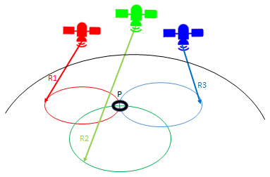
Remarks: GP represent that it is a GPS position (GL would denote GLONASS). Here a proposal how to parse the line "hand-knitted": Program:[►] # Serial4.py import serial port = "/dev/ttyAMA0" # Raspberry Pi 2 #port = "/dev/ttyS0" # Raspberry Pi 3 def parseGPS(data): # print "raw:", data if data[0:6] == "$GPGGA": s = data.split(",") if s[7] == '0': print "no satellite data available" return time = s[1][0:2] + ":" + s[1][2:4] + ":" + s[1][4:6] lat = decode(s[2]) dirLat = s[3] lon = decode(s[4]) dirLon = s[5] alt = s[9] + " m" sat = s[7] print "Time(UTC): %s-- Latitude: %s(%s)-- Longitude:%s(%s)\ -- Altitute:%s--(%s satellites)" %(time, lat, dirLat, lon, dirLon, alt, sat) def decode(coord): # DDDMM.MMMMM -> DD deg MM.MMMMM min v = coord.split(".") head = v[0] tail = v[1] deg = head[0:-2] min = head[-2:] return deg + " deg " + min + "." + tail + " min" ser = serial.Serial(port, baudrate = 9600, timeout = 0.5) while True: data = ser.readline() parseGPS(data) Remarks: It is interesting to know the principles of GPS: The GPS receiver determines the distances to at least 3 GPS satellites and calculates the location with triangulation:
|