![]()
The source code of all examples can be downloaded from here.
Introduction |
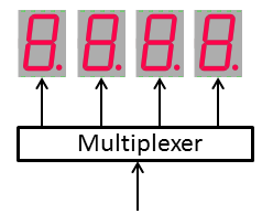
Visual output indicators are widely used in microprocessor systems to provide system information. They may consist of simple LEDs that are switched on continuously or are blinking/dimmed in different rhythms. LED arrays may be arranged in lines or in two dimensions such as 7-segment displays. Finally full alphanumeric and graphics screens are available in different formats. Except the most simple LED displays, the code to handle the display is not trivial and often put in some special software library, called a display driver. It is recommended to add a simple optical indicator to every microcontroller system and we will emphasize here on 7-segment displays that are a good compromise between simplicity and versatility. More complicated alphanumeric displays will be treated later on. A 7-segment display consists of 7 LEDs (+ eventually a decimal point). So an array of 4 displays needs 28 digital output ports, too many for the Raspberry Pi GPIO. There are different options to reduce the amount of data needed to drive the display. Time multiplexing:
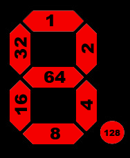
Encoding:
With this encoding, the information for displaying the 4 digits (including 4 decimal points) is 4 bytes. (If you want to know more about the character mapping and which ASCII characters can be displayed, download the mapping sheet.) Serial data communication: The I2C protocol requires only 3 wires: GND, SDA (serial data), SCL (serial clock). The bus master (normally the microprocessor) sends serialized bits over the SDA line. SCL is used to synchronize the master and slave devices. Each slave is identified by its I2C address that is 7 bit wide (0x00 to 0x7F). After you attached an I2C device to the GPIO, you may detect its address by calling i2cdetect -y 1 from a Linux terminal (use -y 0 for old Raspberry Pi Revision A). Sometimes the 8th bit with value 0 is considered to be part of the address. Because it is the LSB, the 8 bit address range is 0x00 to 0xFF with even steps. Example: 7 bit address: 0x38 = 0111000 -> 8 bit address = 01110000 = 0x70. So every time you use an I2C address, inform you if it is a 7 or 8 bit address. In Python, most of the time the SMBus-library is used where device addresses defined as 7 bit addresses. A function summery is given here. A simple device detection program in Python sends a smbus read_byte() command. If a exception is thrown, the device is at the given address in not present. Program to discover I2C devices :[►] # I2CDetect.py import smbus def getI2CDevices(): bus = smbus.SMBus(1) addresses = [] for address in range(128): try: bus.read_byte(address) addresses.append(address) except: pass return addresses print "Found I2C devices at:" devices = getI2CDevices() for address in devices: print("0x" + format(address, "02X")) |
Experiment 1: Using the Didel PyTell display |
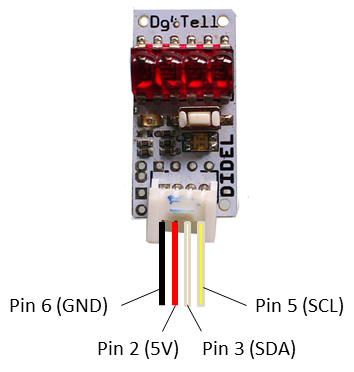
Source of supply: PyTell display (http://www.didel.com). A set of demonstration examples and the PyTell driver library can be downloaded from here. PyTell is a low power miniature 4 digit display that works from 3V (@20mA) to 5.5V (@30mA). The devices uses a very simple data protocol over the I2C bus and its own PIC microcontroller dispatches the incoming 4 bytes. So the GPIO bus is completely freed after the data is transferred. Aim: Circuitry:
Program to display "0123":[►] # Display1a.py # Write 4 bytes (integers) import smbus i2c_address = 0x20 bus = smbus.SMBus(1) # RPi revision 2 (0 for revision 1) cmd = 1 # segment mode data = [63, 6, 91, 79] # 0123 bus.write_block_data(i2c_address, cmd, data) Remarks: Program to display "run", then counting up numbers to 1000 and "donE" Program: [►] # Display1b.py import smbus import time PATTERN = {' ': 0, '!': 134, '"': 34, '#': 0, '$': 0, '%': 0, '&': 0, '\'': 2, '(': 0, ')': 0, '*': 0, '+': 0, ',': 4, '-': 64, '.': 128, '/': 82, '0': 63, '1': 6, '2': 91, '3': 79, '4': 102, '5': 109, '6': 125, '7': 7, '8': 127, '9': 111, ':': 0, ';': 0, '<': 0, '=': 72,'>': 0, '?': 0,'@': 93, 'A': 119,'B': 124,'C': 57, 'D': 94, 'E': 121, 'F': 113, 'G': 61, 'H': 118, 'I': 48, 'J': 14, 'K': 112, 'L': 56, 'M': 85, 'N': 84, 'O': 63, 'P': 115, 'Q': 103, 'R': 80, 'S': 45, 'T': 120, 'U': 62, 'V': 54, 'W': 106, 'X': 73, 'Y': 110, 'Z': 27, '[': 57, '\\': 100, ']': 15, '^': 35, '_': 8, '`': 32, 'a': 119, 'b': 124, 'c': 88, 'd': 94, 'e': 121, 'f': 113, 'g': 61, 'h': 116, 'i': 16, 'j': 12, 'k': 112, 'l': 48, 'm': 85, 'n': 84, 'o': 92, 'p': 115, 'q': 103, 'r': 80, 's': 45, 't': 120, 'u': 28, 'v': 54, 'w': 106, 'x': 73, 'y': 110, 'z': 27, '{': 0, '|': 48, '}': 0, '~': 65} def toSegment(text): data = [] for c in text: data.append(PATTERN[c]) return data i2c_address = 0x20 bus = smbus.SMBus(1) # RPi revision 2 (0 for revision 1) cmd = 1 # segment mode text = "run " data = toSegment(text) bus.write_block_data(i2c_address, cmd, data) time.sleep(3) for i in range(1001): text = "%4d" %i # right adjusted data = toSegment(text) bus.write_block_data(i2c_address, cmd, data) time.sleep(0.01) time.sleep(3) text = "donE" data = toSegment(text) bus.write_block_data(i2c_address, cmd, data) Remarks: Program to show scrolling and blinking text. [►] # Display1c.py from pytell import PyTell import time pt = PyTell() pt.showText("run") time.sleep(3) text = "HELLO Python" pt.showTicker(text, count = 2, speed = 4, blocking = True) text = "8ye" pt.showBlinker(text, dp = [0, 0, 0, 1], count = 4, speed = 2, blocking = True) Remarks: |
Experiment 2: Using the 4tronix Pi2Go display |
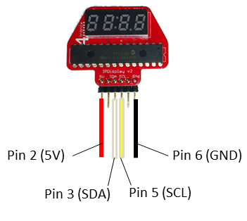
Source of supply: IP Display Dongle/7-Segment Display (http://www.4tronix.co.uk/store) This 4 digit 7-segment array is mainly used to display the IP address when the Pi2Go robot attaches to a WLAN hotspot. But it can also be used as general purpose display without the Pi2Go robot. Like the PyTell display the I2C protocol is used to transfer data, but it uses the MCP23017 16-bit I/O Expander chip to provide the necessary number of digital output lines to select and drive one of the digits. To show all 4 digits at the same time, multiplexing is needed. Aim: Circuitry:
Like many other I2C interfaces, the MCP23017 uses a control register to select the mode of operation. It is always a cumbersome work to investigate how to use it. Without detailed explanation we show in the programs how to setup the display using SMBus. Program displays one character after the other: [►] # Display2a.py from smbus import SMBus import time def setup(): bus.write_byte_data(i2c_address, 0x00, 0x00) # Set all of bank 0 to outputs bus.write_byte_data(i2c_address, 0x01, 0x00) # Set all of bank 1 to outputs def setValue(val, digit): ''' @param digit: 0: leftmost digit @param val: 0..255: segment value ''' n = (1 << (3 - digit)) ^ 255 bus.write_byte_data(i2c_address, 0x13, n) bus.write_byte_data(i2c_address, 0x12, val) i2c_address = 0x20 bus = SMBus(1) # For revision 2 Raspberry Pi setup() word = [118, 119, 56, 63] # HALO for i in range(4): setValue(word[i], i) time.sleep(2) Remarks: setup() word = [118, 119, 56, 63] # HALO while True: for i in range(4): setValue(word[i], i) time.sleep(0.002) setValue(0, i) time.sleep(0.002) This is quite a heavy burden for the processor, so using a on-board microcontroller like in the PyTell display is much better. Again it is a programming challenge to write a display driver that handles the multiplexing internally and allows text scrolling and blinking. Download the module Disp4tronix.py (and some useful demonstration examples) from here and copy it into the directory where your programs reside. You may then explore the nice display features. Program to show scrolling and blinking text. [►] # Display2c.py from Disp4tronix import Disp4tronix import time dp = Disp4tronix() dp.showText("run") time.sleep(3) text = "HELLO Python" dp.showTicker(text, count = 2, speed = 4, blocking = True) text = "8ye" dp.showBlinker(text, dp = [0, 0, 0, 1], count = 4, speed = 2, blocking = True) Remarks: |
Experiment 3: Using your home-brew 4 digit 7-segment display |
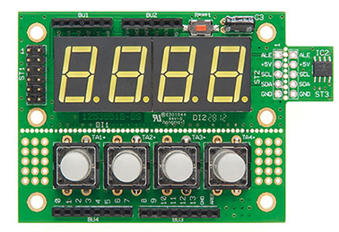
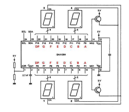
Source of supply: 7-Segment-Anzeige, order # 105697 (http://www.elv.de) You can also build the display from scratch using the SAA1064 4-digit LED-driver with I2C-bus interface. Schematics are found by an Internet search. Unfortunately the SAA1064 IC in DIL and SMD package is no longer fabricated. But you find many suppliers on Ebay or you may purchase a complete display kit including a 4 button panel, a I2C temperature module and several types of front panels from ELV Germany.
Aim: Circuitry: The address selections is performed by a voltage divider that delivers the voltage of the ADR input as follows:
So if the ADR pin is set to GND, the 7-bit address 0x38 is selected. The two extra transistors can be any standard NPN-type (e.g. BC547, 2N2222, etc.) The display may be driven from the 5V supply of the Raspberry Pi (GPIO pin # 2). The SDA and SCL lines are connected directly to the GPIO #3 and #5 with no harm, even if the display is powered with 5 V (no level shifter or pull-up resistor needed).
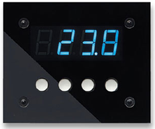
The ELV panel that combines the 4-digit 7-segment display and 4 push buttons is well-designed to be used in a home-automation project with the Raspberry Pi as controller unit. In principle, programming the display is straight-forward, but somewhat tricky when using the SMBus library. The following examples provide the know-how for you. Program to display "0123":[►] # Display3a.py import smbus import time i2c_address = 0x38 bus = smbus.SMBus(1) # RPi revision 2 (0 for revision 1) def setup(): instruction_byte = 0x00 control_byte = 0b00010111 # b0 = 1: dynamic mode (autoincrement digits) # b1 = 1: digit 1/3 not blanked, b2 = 1: digit 2/4 not blanked # b4 = 1: 3 mA segment current # write to control register bus.write_byte_data(i2c_address, instruction_byte, control_byte) def clear(): bus.write_i2c_block_data(i2c_address, 1, [0, 0, 0, 0]) setup() data = [63, 6, 91, 79] # 0123 # write starting from digit 1 bus.write_i2c_block_data(i2c_address, 1, data) time.sleep(5) clear() Remarks: Program to display "run", then counting up numbers to 1000 and "donE"[►] # Display3b.py import smbus import time PATTERN = {' ': 0, '!': 134, '"': 34, '#': 0, '$': 0, '%': 0, '&': 0, '\'': 2, '(': 0, ')': 0, '*': 0, '+': 0, ',': 4, '-': 64, '.': 128, '/': 82, '0': 63, '1': 6, '2': 91, '3': 79,'4': 102, '5': 109, '6': 125, '7': 7, '8': 127, '9': 111, ':': 0, ';': 0, '<': 0, '=': 72, '>': 0, '?': 0, '@': 93, 'A': 119, 'B': 124, 'C': 57, 'D': 94, 'E': 121,'F': 113, 'G': 61, 'H': 118, 'I': 48, 'J': 14, 'K': 112, 'L': 56, 'M': 85, 'N': 84, 'O': 63, 'P': 115, 'Q': 103, 'R': 80, 'S': 45, 'T': 120, 'U': 62, 'V': 54, 'W': 106, 'X': 73, 'Y': 110, 'Z': 27, '[': 57, '\\': 100, ']': 15, '^': 35, '_': 8, '`': 32, 'a': 119, 'b': 124, 'c': 88, 'd': 94, 'e': 121, 'f': 113, 'g': 61, 'h': 116, 'i': 16, 'j': 12, 'k': 112, 'l': 48, 'm': 85, 'n': 84, 'o': 92, 'p': 115, 'q': 103, 'r': 80, 's': 45, 't': 120, 'u': 28, 'v': 54, 'w': 106, 'x': 73, 'y': 110, 'z': 27, '{': 0, '|': 48, '}': 0, '~': 65} i2c_address = 0x38 bus = smbus.SMBus(1) def setup(): instruction_byte = 0x00 control_byte = 0b00010111 # b0 = 1: dynamic mode (autoincrement digits) # b1 = 1: digit 1/3 not blanked, b2 = 1: digit 2/4 not blanked # b4 = 1: 3 mA segment current # write to control register bus.write_byte_data(i2c_address, instruction_byte, control_byte) def toSegment(text): data = [] for c in text: data.append(PATTERN[c]) return data setup() text = "run " data = toSegment(text) bus.write_i2c_block_data(i2c_address, 1, data) time.sleep(3) for i in range(1001): text = "%4d" %i # right adjusted data = toSegment(text) bus.write_i2c_block_data(i2c_address, 1, data) time.sleep(0.01) time.sleep(3) text = "donE" data = toSegment(text) bus.write_i2c_block_data(i2c_address, 1, data) Remarks: Program to show scrolling and blinking text. [►] # Display3c.py from py7seg import Py7Seg import time ps = Py7Seg() ps.setBrightness(7) ps.showText("run") time.sleep(3) text = "HELLO Python" ps.showTicker(text, count = 2, speed = 4, blocking = True) text = "8ye" ps.showBlinker(text, dp = [0, 0, 0, 1], count = 4, speed = 2, blocking = True) |
Experiment 4: Using an alphanumeric/graphics display |
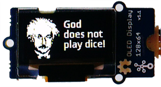
Compared to a simple 4-digit display an alphanumeric or even a pixel-based graphics display opens a new dimension for the user interaction. In the field of embedded systems OLED displays are more and more used because of their high contrast ratio and low power consumption.
As you may expect, the communication with the SSD1306 controller is somewhat laborious. Fortunately Tony DiCola from Adafruit wrote a Python driver that handles all low-level (register based) tasks. Because it uses a GPIO port to reset the display that is not needed for most devices, we modified it slightly and distribute the driver as SSD1306.py. In addition we added a thin software layer OLED1306.py to simplifiy the use of the OLED display to a maximum. Both modules (and some text fonts, example scripts and pictures) can be downloaded from here. Program to show a single line: [►] # Display4a.py import RPi.GPIO as GPIO from OLED1306 import OLED1306 disp = OLED1306() disp.setText("Hello Python") To display a graphics, the image file should have PPM format with a 128x64 bitmap (B/W) size. You may edit the picture using Photoshop. Use and modify one of the example pictures to get acquainted to the special format requirements. Program to show a picture /home/pi/Pictures/einstein.ppm mixed with text:[►] # Display4b.py from OLED1306 import OLED1306 disp = OLED1306("/home/pi/Pictures/einstein.ppm") disp.setText("God\ndoes not\nplay dice!", 0, 15, 60) # Parameters: text, line number, font size, indent (pixels) The OLED1306 module also supports console-like text scrolling. Program to show automatic line scrolling:[►] # Display4c.py from OLED1306 import OLED1306 import time disp = OLED1306() nb = 1 while True: disp.println("Line #" + str(nb)) nb += 1 time.sleep(0.5) To get information about all features of the class OLED1306 consult the Python documentation. Be aware that as default the OpenSans font family is used that is assumed to be located in /home/pi/Fonts. |
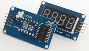
Experiment 5: Using the cheap TM1637 4-digit display |
Program: Perpetual counter 0..9999 [►] from TM1637 import FourDigit d = FourDigit() while True: for n in range(10000): d.show(n) Highlight program code
It's very easy to display a scrolling text. The methods toLeft() and toRight() provides more more freedom than scroll(), which blocks until the text is completely displayed. Program: Scroll text (endless) [►] from TM1637 import FourDigit d = FourDigit() while True: d.scroll("HELLo PYthon") Highlight program code
As a useful application, the display shows the current time (hours/minutes) with the colon flashing every second. The current time is delivered by the real-time clock DS1307, as described in the chapter Timers. There you also find how to preset the clock. Program: Digital clock [►] from RTC_DS1307 import RTC from time import sleep from TM1637 import FourDigit d = FourDigit() rtc = RTC() showColon = True while True: hr = rtc.getHours() min = rtc.getMinutes() d.show("%02d%02d" %(hr, min)) d.setColon(showColon) showColon = not showColon sleep(0.5) In order to display leading zeros for 1-digit hours and minutes, the string formatter %02d is used.
|