![]()
The source code of all examples can be downloaded from here.
DC motor control using a H-bridge |
|
| |||||||||||||||||||||||||||||||||||||||||||||||||||
|
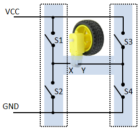
A DC motor represents a wonderful application of one of the most fundamental law of physics expressing that a moving charge, here the electrons of a current in a wire, experiences a force when a magnetic field is applied. In other word, if a current flows through a wire that near a magnet, the wire experiences a force. By the special motor construction this force is converted to a torque that turns the rotor shaft. If the current is reversed the shaft turns in the opposite direction. To reverse the direction of the current flow, an arrangement that resembles to the letter 'H' is used, called a H-bridge is used. Its functional diagram looks like this:
By acting the switches, the motor input voltage at X, Y can be zero or have X+, Y- or X-, Y+ polarity.
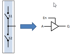
Not all switch combinations are allowed, because by closing S1 and S2 or S3 and S4, you cause a short-circuit. In electronics each side of the H-bridge is built by a current driver that pulls the output Q to either GND or VCC or let it open (3 states). The circuit has two inputs A and En (Enable) and an output Q. It is called "Half H-Bridge". Half H-Bridge:
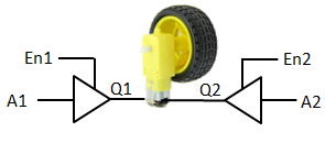
The equivalent of the H-Bridge to drive the motor looks like this:
But since the motor is powered by the voltage between Q1 und Q2, it also stops when Q1 equals Q2. As consequence the enable inputs En1 and En2 can be constantly set to high (enable) and the motor is controlled by the two inputs A1 and A2:
|
|
|
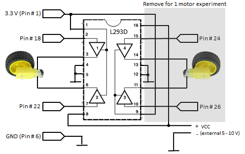
Experiment 1: Forward/backward control of two motors |
Caution: Do never connect a DC motor directly to the GPIO ports because voltage spikes occur caused by induction when the motor is switched off. Wiring:
Program:[►] # Motor1.py # Motor forward & backward import RPi.GPIO as GPIO import time P_MOTA1 = 18 P_MOTA2 = 22 def forward(): GPIO.output(P_MOTA1, GPIO.HIGH) GPIO.output(P_MOTA2, GPIO.LOW) def backward(): GPIO.output(P_MOTA1, GPIO.LOW) GPIO.output(P_MOTA2, GPIO.HIGH) def stop(): GPIO.output(P_MOTA1, GPIO.LOW) GPIO.output(P_MOTA2, GPIO.LOW) def setup(): GPIO.setmode(GPIO.BOARD) GPIO.setup(P_MOTA1, GPIO.OUT) GPIO.setup(P_MOTA2, GPIO.OUT) print "starting" setup() while True: print "forward" forward() time.sleep(2) print "backward" backward() time.sleep(2) print "stop" stop() time.sleep(2) Remarks: If you use small 5-6 V motors like the Micro Metal Gear motors (from Pololu, PIROMONI and others), they may be powered by the Raspberry Pi 5V DC output (pin #2). |
|
|
Experiment 2: Speed control with PWM |
|
Aim: Consult the tutorial about LED dimming to learn how to handle PWM. Circuitry: Program:[►] # Motor2.py # Motor speed & direction import RPi.GPIO as GPIO import time P_MOTA1 = 18 P_MOTA2 = 22 fPWM = 50 # Hz (not higher with software PWM) def forward(speed): pwm1.ChangeDutyCycle(speed) pwm2.ChangeDutyCycle(0) def backward(speed): pwm1.ChangeDutyCycle(0) pwm2.ChangeDutyCycle(speed) def stop(): pwm1.ChangeDutyCycle(0) pwm2.ChangeDutyCycle(0) def setup(): global pwm1, pwm2 GPIO.setmode(GPIO.BOARD) GPIO.setup(P_MOTA1, GPIO.OUT) pwm1 = GPIO.PWM(P_MOTA1, fPWM) pwm1.start(0) GPIO.setup(P_MOTA2, GPIO.OUT) pwm2 = GPIO.PWM(P_MOTA2, fPWM) pwm2.start(0) print "starting" setup() for speed in range(10, 101, 10): print "forward with speed", speed forward(speed) time.sleep(2) for speed in range(10, 101, 10): print "backward with speed", speed backward(speed) time.sleep(2) print "stopping" stop() GPIO.cleanup() print "done" Remarks: |
|
|
Experiment 3: Motor control with rotation encoders |
|
(to be done) |