![]()
The source code of all examples can be downloaded from here.
The temperature is one of the most important physical quantities to be measured in technical systems. There are many different types of temperature sensors: Some of them deliver a voltage directly, other transforms temperature changes to another quantity that is then converted to a voltage. Many modern temperature sensors are integrated with electronic circuits in a single package and output the temperature directly as digital data in a well-established protocol (typically I2C, SPI or 1-Wire). |
Thermistors |
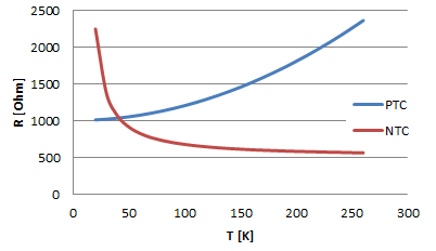
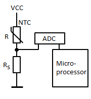
Thermistors are thermally sensitive resistors. The relation between temperature T and resistance R is highly non-linear. Most thermistors have a Negative Temperature Coefficient (NTC) and exhibit a decrease of the resistance with increasing temperature. The characteristic can be approxmated by a decreasing exponential function. Also Positive Temperature Coefficient thermistors (PTC) are available. In most cases the resistance changes are converted to voltage changes using the sensor as part of a voltage divider. In data processing systems the output voltage is then fed into a ADC and data transferred to a microprocessor.
(R and RS may be interchanged) Aim: Circuitry: Program: (to be done) Remarks:
Thermistors are widely use to detect a certain temperature level, e.g. to stabilize the temperature in a heater, refrigerator, etc. In these applications the absolute value of the temperature is of less importance. |
IC Based Sensors With Analog Output |
|
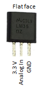
Temperature measurement is very important in many situations, as consequence temperature sensors comes in many different flavors. The LM35 family and TMP35/36/37 are integrated circuit sensors that can be used to measure temperature in quotidian range with a voltage output that is linear with the temperature. The scale factor is 10-20 mV/degree.
The program displays the current temperature in degrees centigrade. Consider the following conversion: Since the sensor delivers a = 10 mV = 0.01 V per degrees centigrade, the output voltage is u = a * T. If the voltage u is applied to the 10-bit ADC powered with 3.3V, the digitized value returned to the program is v = u / 3.3 * 1023. So the relation between the temperature and the value returned from the ADC is v = 0.01 / 3.3 * 1023 * T = 3.1 * T. Program:[►] # RaspEasy7c.py # LM35 temperature sensor import smbus import time #from OLED1306 import OLED1306 def readData(port = 0): if port == 0: adc_address = 0x48 elif port == 1: adc_address = 0x4D rd = bus.read_word_data(adc_address, 0) data = ((rd & 0xFF) << 8) | ((rd & 0xFF00) >> 8) data = data >> 2 return data print "starting..." #oled = OLED1306() #oled.setFontSize(50) bus = smbus.SMBus(1) while True: v = readData() T = v / 3.1 print "T = %4.1f centigrades" %T # oled.setText(str(int(T + 0.5))) # rounded to int time.sleep(1) |
IC Based Sensors With Digital Output |
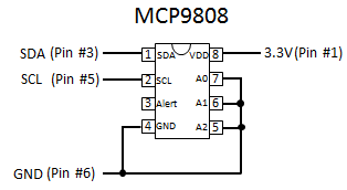
As you can see in the datasheet, a single I2C word read is necessary to get a temperature value. The data is encoded in the 16 bits returned by the SMBus read_word_data() function and some bit juggling is needed to extract the temperature. The datasheet contains a sample program that explains exactly what to do. It is ported to Python with explicatory comments in the following program. Program:[►] # Temp3.py # Temperature sensor MCP9808 import smbus import time i2c_address = 0x18 temp_register = 0x05 def readTemp(): v = bus.read_word_data(i2c_address, temp_register) hiByte = v & 0x00FF # SMBus with reversed byte order loByte = (v >> 8) & 0x00FF hiByte = hiByte & 0x1F # clear flag bit if hiByte & 0x10 == 0x10: # temp < 0 hiByte = hiByte & 0x0F # clear sign temp = 256 - hiByte * 16 + loByte / 16.0 # scale else: temp = hiByte * 16 + loByte / 16.0 # scale return round(temp, 1) print "starting..." bus = smbus.SMBus(1) while True: t = readTemp() print "T =", t, "centigrades" time.sleep(1) Highlight program code
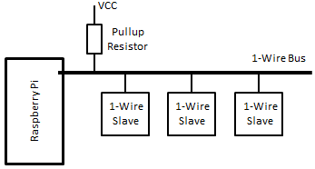
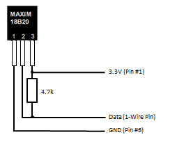
Temperatur Sensor with 1-Wire bus The DS18B20 can be used as digital thermometer in the range of -55 to 125 oC with +- 0.5 oC accuracy. Since it can be connected directly to the GPIO of the Raspberry Pi, it is the ideal solution for indoor and outdoor temperature measurements. The sensor communicates with the Raspberry Pi with the 1-Wire communication protocol developed by Dallas Semiconductor. The protocol uses a single line (and ground) that is also called a bus, because every device is connected to it either as listener (high impedance) or as transmitter (pulling it down to ground for some time). The Raspberry Pi acts as the bus master and many bus slaves may be connected to the same line. In idle state, the bus is hold HIGH by a pull-up resistor and all connected slaves are listening.
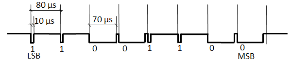
The master then calls a slave by its address (8 bytes) which is unique for each slave device. To write a logic “1”, the bus line is pulled to ground for 1-15us, to write a logic “0", the bus is low for 60-120 us. To get a reply, the masters enters the listening state and the slave transmits data in the same format. So master and slaves can be transmitters and receivers, but only in one direction at a time. Follows an example of timing to send the byte b0011'0011 = 0x33 (LSB is sent first):
The protocol can be compared with Morse code, where dots and dashes are used. It can also be considered as a kind of Pulse Width Modulation PWM. The address is composed of a 1-byte family code, a 6 byte ID and a 1 byte CRC. It is very simple to enable the 1-Wire protocol for the DS18B20 sensor with the current version of the NOOBS distribution, becauce the driver is part of the kernel. (In the current RaspiBrick SD-card distribution, 1-Wire protocol is already enabled for GPIO 4 (pin #7.) To activate the driver yourself, edit the file /boot/config.txt: sudo nano /boot/config.txt and add the line dtoverlay=w1-gpio,gpiopin=4 (Set the gpiopin parameter for the GPIO pin you want to reserve. If you omit it, the defaut port GPIO 4 (pin # 7) is used.) Connect the 1-Wire slave device and reboot. Keep in mind that the 1-wire GPIO I/O port should not be used as normal I/O port from now on. Aim:
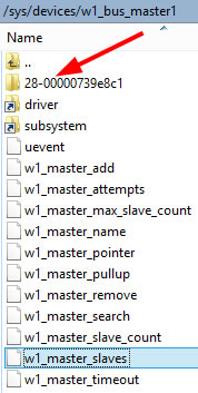
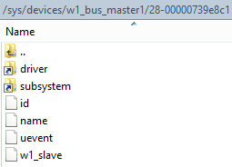
Program:[►] # Temp1.py import time from py7seg import Py7Seg # xxx masterFolder = "/sys/devices/w1_bus_master1/" def getSlaveFolders(): # Get list of all 1-Wire slave folders file = open(masterFolder + "w1_master_slaves") slaveFolders = file.read().splitlines() file.close() return slaveFolders def getTemperature(slaveFolder): # Read content of corresponding w1_slave file. Format: # 6f 01 4b 46 7f ff 01 10 67 : crc=67 YES # 6f 01 4b 46 7f ff 01 10 67 t=22937 file = open(masterFolder + slaveFolder + '/w1_slave') lines = file.read().splitlines() file.close() # Extract temperature from second line temperature = float(lines[1][29:]) / 1000 return temperature ps = Py7Seg() # xxx slaveFolders = getSlaveFolders() while True: # Extract temperature from first slave temp = getTemperature(slaveFolders[0]) print("T = %6.2f deg" %temp) w = "%4.1f" %temp ps.showText(w[0] + w[1] + w[3] + '#'], dp = [0, 1, 0]) time.sleep(1) Remarks: You will not get temperature values more frequent than about every second, because getTemperature() blocks until a new value is written in the file. If you do not have a ELV display or you use another display, comment out or modify the lines marked with xxx.
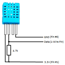
Temperatur and Humidity Sensor with 1-Wire bus The DHT11, DHT22 (also called AM2302) are modules that measure temperature and humitiy and transfer the digitized values over a 1-Wire bus. To use them with the Raspberry Pi, a 1-Wire driver written in C/C++ has to be used, because of the tight requirements for the timing using short pulses in the order of 10-100 us. At the moment two driver sources are available, one from Adafruit und one that is part of the pigpio library. The installation process for both packages is simple, but the pigpio version needs a daemon to be started before the user program runs. To install the package from Adafruit you may follow the instructions from their homepage (http://www.adafruit.com). The software is already installed in the current version of our Raspibrick SD card distribution. Aim:
Program:[►] # DHT1.py import Adafruit_DHT import time from py7seg import Py7Seg # xxx ps = Py7Seg() # xxx SENSOR_TYPE = Adafruit_DHT.DHT11 P_DHT = 4 # GPIO numbering (Pin # 7) while True: hum, temp = Adafruit_DHT.read_retry(SENSOR_TYPE, P_DHT) if temp == None: t = "--.-" else: t = "%2.1f" %temp if hum == None: h = "--.-" else: h = "%2.1f" %hum print "Temperature", t, "Humitity", h ps.showText("t" + t[0] + t[1] + t[3], dp = [1, 0, 0]) # xxx time.sleep(3) ps.showText("h" + h[0] + h[1] + h[3], dp = [1, 0, 0]) # xxx time.sleep(3) |